Introduction
We run a weekly coding dojo at work, and I thought implementing an Enigma machine simulator might make an interesting problem, so I spent a few evenings reading up about how the machines worked. Unfortunately my attempt to explain it all in a few minutes was … let’s just say somewhat less than successful. This is an attempt at a better explanation!
You can find my solution (in Ruby) in the github repo that this site is attached to.
If you want to read a bit more about the workings of a real Enigma machine, here are my main sources of information:

“EnigmaMachineLabeled”. Licensed under Public Domain via Wikimedia Commons.
The problem
Your task is to implment a simulator for the Enigma I (Army/Wehrmacht) enycryption machine. Once you have this model simulated, it should be relatively simple to expand it to other variants, such as those with more rotors, multiple turnover notches or repositionable reflector wheels (don’t worry, those terms should make sense soon). While building your solution, keep this expandability in mind – without prematurely generalising, does your design separate the various concerns in such a way that new features should fit in neatly?
The program you write should take a string of plaintext, and return a string of cyphertext (or vice versa – the encryption is symmetrical, so feeding the cyphertext into a machine with the same initial settings as were used for encryption will output the original text).
So how does it work?
To simplify things, we’re going to show a machine that only has an alphabet of four letters (the real one has 26, as should your simulation). Also, in the diagrams below, the rotors have been “unrolled” – imagine that the top of each rotor joins up with the bottom to form a circle.
Components
This diagram illustrates the six main components of the machine:
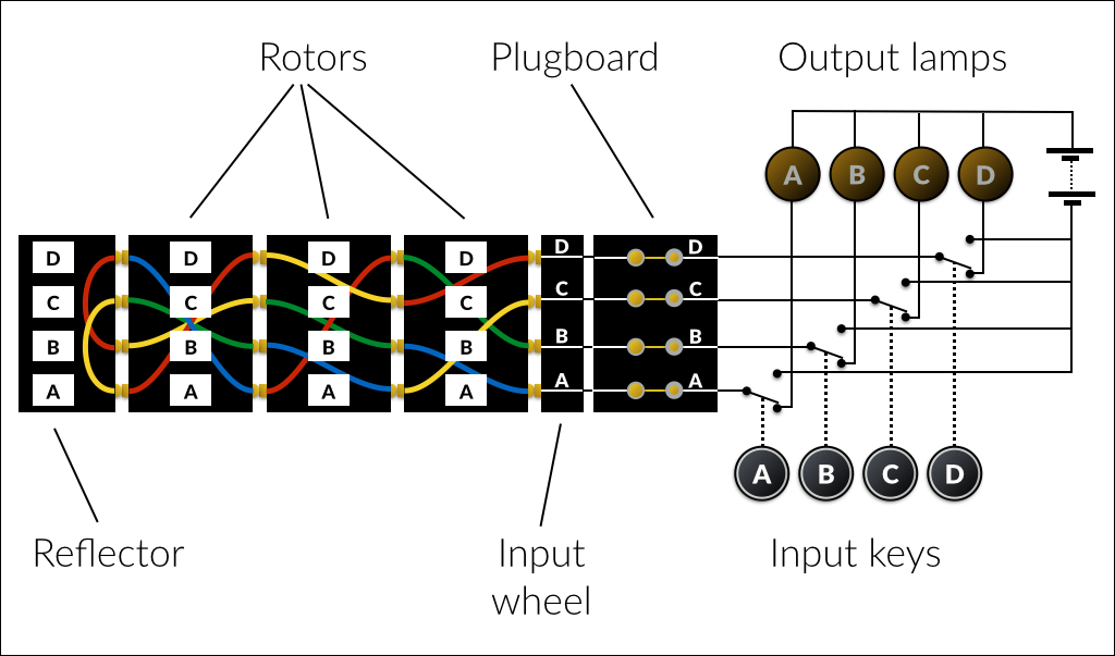
Input keys
This is where the text to be encrypted is entered, one letter at a time. The switches and electrical circuit are shown for completeness, but for the simulation you only need to treat it as one letter going in and a different one coming out. Interestingly, because of the way the signal is reflected up and down the machine, it is always a different letter – a letter is never encrypted to itself. This was one of the flaws that made the cypher easier to break.
Plugboard
This was an addition to the original Enigma design for the army version. It has a pair of sockets for each letter, which by default are simply connected together, so each of the 26 outputs lines up with its corresponding input. However, the machine came with a number of patch cables, with a double plug on each end. When inserted between the socket pairs for two letters, the default connection is broken and the two letters are swapped. For example, here a cable has been connected between A and B:
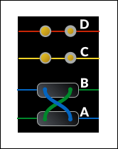
With this configuration, if the operator typed an A, then it would arrive in the main part of the machine as a B (and vice versa). Because of the back-and-forth nature of the machine, any patch cabless on the plugboard also swap the connection to the output lamps.
Up to 13 patch cables (or none) could be used at once, but the German army procedures generally used ten.
You may want to ignore the plugboard to begin with, and add it once you have the basic rotor system working.
Input wheel
This simply connects the plugboard outputs to a ring of 26 contacts which correspond to the contacts on the rotors. The Enigma I just mapped A to the first position, B to the second and so on, although some other models used German keyboard order (QWERTZU), and a few used other mappings.
You may choose not to explicitly model the input wheel – it’s up to you.
Rotors

“Enigma rotors with alphabet rings” by TedColes - Own work. Licensed under CC0 via Wikimedia Commons.
These, unsurprisingly, form the heart of the Enigma algorithm. The Enigma I, like most variants, used three rotors.
Each rotor has 26 contacts in a ring around each side, and is marked with the 26 letters of the alphabet around the circumference. The contacts are internally wired so that the contact on the right corresponding to one letter connects to the contact on the left next to a different letter.
Here’s our diagram from earlier again:
Looking at the rotor on the right, we see that A maps to B, B to D, C to A and
D to C. This is effectively just a simple Caesar
cypher, mapping our truncated
alphabet ABCD to BDAC. This would normally be described as simply BDAC
– the list of positions on the left corresponding to the normal ordered
alphabet on the right. The middle wheel in the example has a mapping of BCDA,
and the one on the left DCBA.
The Enigma I initially came with three rotors, which could be fitted in any order. Their mappings were as follows:
A B C D E F G H I J K L M N O P Q R S T U V W X Y Z | |
|---|---|
| I: | E K M F L G D Q V Z N T O W Y H X U S P A I B R C J |
| II: | A J D K S I R U X B L H W T M C Q G Z N P Y F V O E |
| III: | B D F H J L C P R T X V Z N Y E I W G A K M U S Q O |
Later, two more wheels were introduced (it’s up to you whether your simulator supports these, but adding them should be easy):
A B C D E F G H I J K L M N O P Q R S T U V W X Y Z | |
|---|---|
| IV: | E S O V P Z J A Y Q U I R H X L N F T G K D C M W B |
| V: | V Z B R G I T Y U P S D N H L X A W M J Q O F E C K |
With the cover on the machine, the letter in the first position is visible. This letter indicates the current setting of the wheel, and can be adjusted by turning a grooved wheel on the edge of the rotor, which is also exposed through the cover:
The setting of each rotor forms part of the initialisation of the machine, ensuring the encryption key is different for each message.
As well as the initial settings, the rotors are also advanced by the machine as each letter is encrypted – we’ll get to that shortly.
Reflector
The reflector is single-sided, like the input wheel, but instead of its
contacts being connected externally, they are each swapped in pairs, causing
the signal to return back through the rotors from left to right, along a
different path. Our rotor swaps A with C, and B with D, so using the same
notation as for the rotors, it would be described as CDAB.
The Enigma I was used with various reflectors over time, with the following mappings (UKW stands for Umkehrwalze, or “reversal rotor”):
A B C D E F G H I J K L M N O P Q R S T U V W X Y Z | |
|---|---|
| UKW-A: | E J M Z A L Y X V B W F C R Q U O N T S P I K H G D |
| UKW-B: | Y R U H Q S L D P X N G O K M I E B F Z C W V J A T |
| UKW-C: | F V P J I A O Y E D R Z X W G C T K U Q S B N M H L |
There was also a UKW-D, which allowed the connections to be rewired in the field. Again, you choose which you want to support.
Output lamps
The output lamps simply display the result of encrypting each letter. The operator would write down the letter which lit up for each key that was pressed, until the full message had been encrypted.
Signal path
Let’s recap how the signal travels through the machine. In the diagram below the rotors have been rotated to different positions, and there is a patch cable in place on the plugboard.
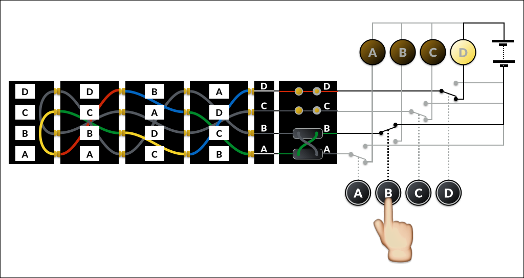
The operator has pressed the B key. We have a patch cable in the
plugboard which swaps A and B, so this enters the
input wheel at A, and is connected to the first
contact of the right-hand rotor (from now on we’ll refer to the contact
positions as 1, 2, 3 and 4,
where 1 is at the bottom of our diagram and 4 at the
top).
The right-hand rotor is in position B, so contact 1
corresponds to its B input. It has a mapping of [ABCD
→ ] BDAC, so B maps to D.
D is in position 3, which is contact with the
A input of the middle rotor.
The middle rotor maps A to B, which enters the left
rotor at D and exits at A. This is in contact with
A on the reflector, which maps to C.
The signal then returns through the left (C to B),
middle (D to C) and right (B to
A) rotors, and out of the input wheel at D.
D is not swapped with anything on the plugboard, so it emerges
unchanged and (finally!) lights the D lamp.
Rotor advance
As mentioned earlier, as well as being manually set to an initial position, the rotors also rotate during encryption. This is accomplished by a set of pawls which operate every time key is pressed (before the circuit is made and an output lamp illuminated). The pawls engage with ratchets on the right-hand side of the rotors, and notches on the left-hand side:

“Enigma rotors and spindle showing contacts rachet and notch” by TedColes - Own work. Licensed under Public Domain via Wikimedia Commons.
Because the pawl between each pair of rotors has to engage with both the ratchet on the rotor to its right and the notch on the one to its left, a rotor is only advanced when the one to its right is in the “turnover” position (ie when its notch aligns with its current position). The right-most rotor has no other rotor to its right, so is advanced with each keystroke.
This diagram shows the sequence through two keystrokes on our simplified machine:
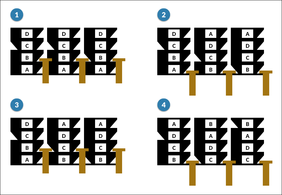
Before first keystroke
The notch on the right-hand wheel is aligned with the pawl, but the one on the middle wheel is not.
After first keystroke
As the pawls pull down, the right-hand rotor is advanced (as it is on every keystroke). The alignment of the notch on the right-hand wheel also allows the second pawl to engage, advancing the middle rotor too. The notch on the middle wheel is not aligned, so the left-hand pawl can’t engage, and slides down without advancing the left-hand rotor.
Before second keystroke
The notch on the right-hand rotor is no longer aligned, but the one on the middle rotor is.
After second keystroke
The right-hand rotor advances, as always. The next pawl can’t engage, so does not move the middle rotor this time. The notch on the middle rotor does line up this time though, allowing the left-hand pawl to engage, advancing both the left and middle rotors.
Note that the middle rotor advanced in both steps – this is a (probably unintended) feature called double stepping. Every time the middle rotor advances to its turnover position – once every 26 × 25 keystrokes – it advances again on the next keystroke.
Here are the rotor details again, with turnover position information added (a
turnover position of Q indicates that turnover will happen when
the rotor moves from Q to R):
A B C D E F G H I J K L M N O P Q R S T U V W X Y Z | Turnover | |
|---|---|---|
| I: | E K M F L G D Q V Z N T O W Y H X U S P A I B R C J | Q |
| II: | A J D K S I R U X B L H W T M C Q G Z N P Y F V O E | E |
| III: | B D F H J L C P R T X V Z N Y E I W G A K M U S Q O | V |
| IV: | E S O V P Z J A Y Q U I R H X L N F T G K D C M W B | J |
| V: | V Z B R G I T Y U P S D N H L X A W M J Q O F E C K | Z |
The main points to note about rotor turnover:
- Rotors advance before encryption happens. So if the left rotor is initially
set to
A, the first letter typed will be encrypted with it in positionB. - Because the pawls operate in unison, no rotor can move more than one position per keystroke.
- When a rotor’s turnover notch is aligned, both that rotor and its left neighbour are advanced.
Ring settings
One more complication, then we’re done!
Up to now, we’ve assumed that the letters were stamped directly on the rims of the rotors, but this is not actually the case. In fact they are on a separate letter ring (or alphabet tyre), which can be rotated relative to the rotor’s internal wiring before inserting the rotor into the machine.
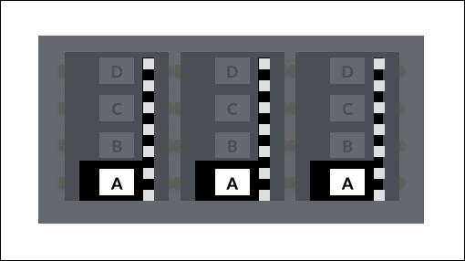
Rotating the ring has the effect of moving each mapping one character forward in the alphabet. That might make more sense with a diagram:
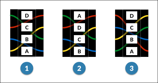
- This is a rotor with its ring in position 1.
- The same rotor with its ring rotated to position 2.
- Still in position 2, but the whole rotor has been rotated back so the letters are in their original positions.
Our rotor has a mapping of BDAC, or in full:
A → B
B → D
C → A
D → C
With the ring rotated one position (from 1 to 2), the letters on both sides of each mapping advance through the alphabet by one position:
B → C
C → A
D → B
A → D
As with the plugboard, you may want to ignore ring settings until you have the basic machine simuation working.
Operation
Operation of the machine is in two phases: setup and encryption.
Setup
The setup would have followed a procedure from a codebook, giving initial settings for each day. The operator would then have chosen a random key for each message, which was sent before the message, either in the clear or encrypted using a different key (you can read more here, although it’s not relevant to the simulator).
Setup comprises the following steps:
- Choose a set of three rotors, and the order in which they will be inserted.
- Set the ring position on each rotor.
- Insert a number of patch cables into the plugboard.
- Choose a three-letter key, and set the initial rotor positions so the letters of the key are showing.
Encryption
Each letter of the message is entered into the machine, and the displayed lamp noted down. The rotors are not manually rotated at any point during encryption.
Because the algorithm is symmetrical, decryption follows exactly the same process. If another machine is initialised to the same settings and the encrypted message typed in, the original plaintext will be output.
Test cases
You might find the following test cases useful. Another good sanity check is to encrypt some text, then configure the web simulator with the same settings and enter your encrypted message. If your code is working correctly, you should get your original text back.
In the following table, rotors, ring settings and start positions all apply left to right, so for example “I III II, 1 2 3, A B C” means that the left position is taken by rotor I in ring position 1, rotated to show “A”, and so on. All examples use reflector UKW-B.
| Rotors | Ring settings | Start positions (key) | Plugboard | Input | Output |
|---|---|---|---|---|---|
| Everything in home position: | III II I |
1 1 1 |
A A A |
— | HELLOWORLD |
MFNCZBBFZM |
| Rotors switched round: | I III II |
1 1 1 |
A A A |
— | HELLOWORLD |
ZXVMIZYFEY |
| Initial rotor settings: | III II I |
1 1 1 |
J X B |
— | HELLOWORLD |
QNDMFRCGTS |
| With plugboard patch cables: | III II I |
1 1 1 |
A A A |
CQ XP |
HELLOWORLD |
MFNQZBBFZM |
| Ring settings: | III II I |
20 13 5 |
A A A |
— | HELLOWORLD |
JCEESPSDYR |
| Turnover: | III II I |
1 1 1 |
A E Q |
— | HELLOWORLD |
NIJMQPUDGW |
| Double stepping: | III II I |
1 1 1 |
A D P |
— | HELLOWORLD |
XUWJPJIBIE |